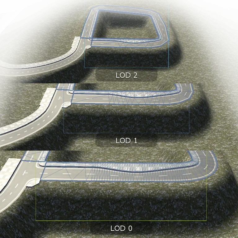
Most road editors in the store use fixed spline detail without any LOD. Therefore, one has to choose between performance and having smooth curves even in the sharpest turns. With benefits of adaptive spline detail and procedurally generated levels of details, you can create large networks with fine detail without overloading your GPU with hundreds of thousands of vertices on roads alone.
Introduction
Adaptive detail of road geometry and LOD generation

Tangent editing
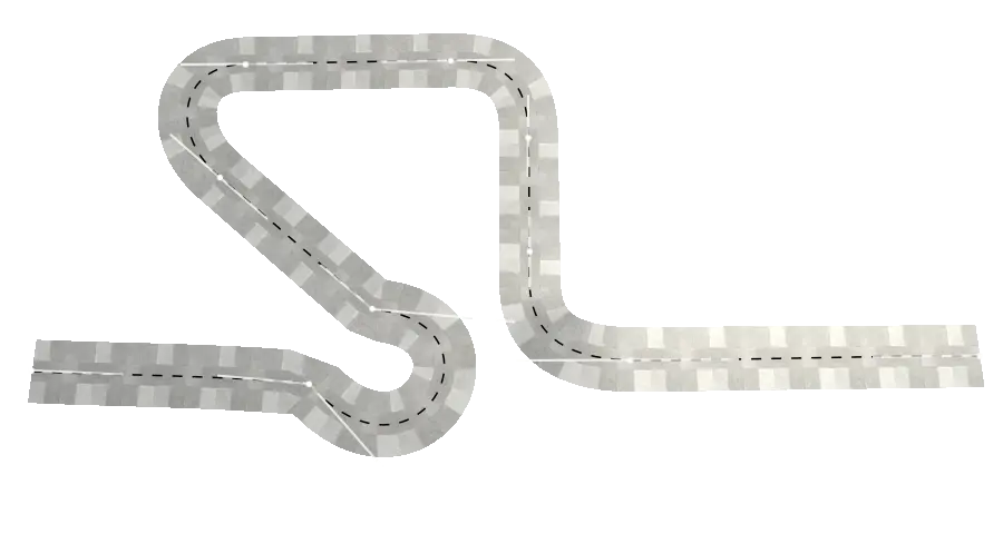
Tangents of curve nodes are typically calculated as average of direction to next and previous nodes. This results in undesirable curve shapes and makes creation of straight segments unfeasible. You will try to remedy that by adding more nodes, which doesn't work.
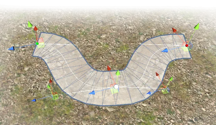
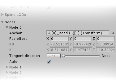
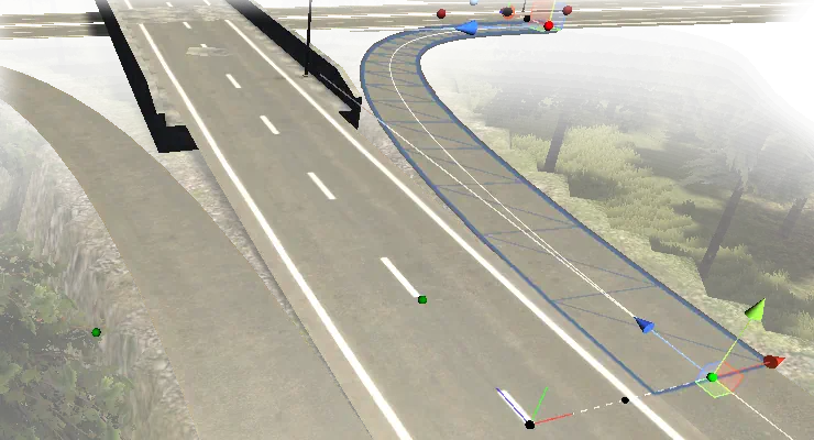
LODRoads allow to blend tangents direction between direction to next and previous nodes. If this is still not enough to achieve your desired result, you can edit the tangents manually, having absolute freedom in determining the shape of the road, as illustrated on following picture.
Node linking
Each spline node can be linked to a Transform object, making both the node's position and tangent relative to the linked Transform. This plain interface enables multiple use-cases: Linking road segments and crossroads to each other, linking roads to custom geometry and possibly even meshes of other road tools. Coupled with position offsetting, merging and joining lanes and multi-level crossroads can be created.
Spline geometry options
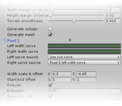
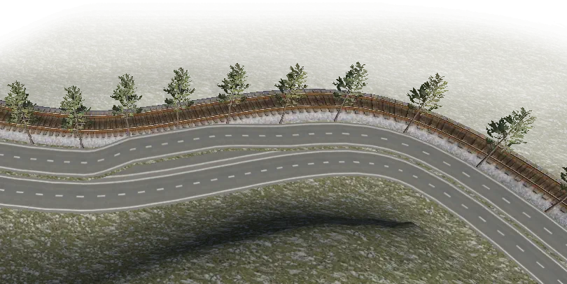
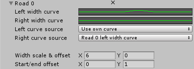
The width of roads and sidewalks can be modulated with custom curves. Roads and sidewalks within one spline can share curves, which allows to easily create roads with choke points or parking places with sidewalks connecting seamlessly to the road.
Creation of railways, walls, pipelines and other line structures is a common feature of road/spline tools, as is spawning of custom prefabs to create light poles or tree alleys. A little addition on top of this is the option to add multiple roads and custom meshes, which enables multilane roads, roads with sidewalks, bridges with roads and sidewalks. Sidewalks with curbs can be generated procedurally, without user-supplied meshes, both on roads and crossroads.

Crossroads and roundabouts
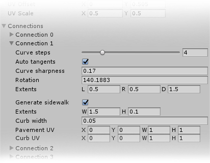
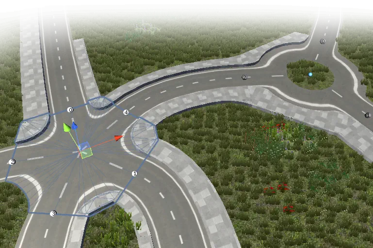
Configurable number and direction of connections, corner sharpness, and UV offset and scale expands the options for road network design. UVs are generated in a way that same materials and textures as on roads could be used. If you need more than the procedural generator can offer, you can use the built-in exporter to save the crossroad as a prefab and enhance its mesh in your favourite 3D modeling software. The exported prefab contains all the link transforms, which lets you easily attach the modified crossroad to the road network.
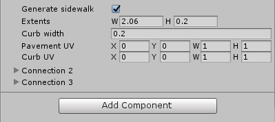
Sidewalks with separate UV configuration for curb and top can be generated between connections.
Future work
Decal painting, which will allow painting crosswalks, road marks and signs, but also cracks and potholes and other textures.
Procedural generation creates a lot of redundant geometry for straight roads or repetitive turns, for example, those that can be found in cities with square road networks. This redundancy can be removed by combining modular and procedural creation of the road system. LODRoads would be extended with controls to assemble, edit and reshape roads as an arbitrary sequence of mesh modules and procedural patches. This is especially important for extruded geometry, like railroads or walls, because those can easily contain hundreds of thousands of unique vertices.
Reverting heightmap changes is unreliable and not user-friendly. The current terrain heightmap painting module is unable to persist heightmap changes, which is currently patched by reverting all LODRoads heightmap changes on scene close and applying them back on scene open. Since detecting scene closed/opened cannot be reliably done in older versions of Unity either, this is again patched by simply reverting heightmap on component disabled, and applying them on component enabled. This causes changes to be reverted on road deleted, on scene recompile, on play and on build, and it still sometimes fails too. Research on how to save terrain heightmaps in Unity seems to be the most promising way to find a solution. The issue of heightmap composition in case of overlapping roads also needs to be adressed. Currently, the heightmap height corresponds to the height of the last applied road, instead of corresponding to the lowest road.
All features
Export
Road networks can be exported as both a mesh and a prefab. The advantage over general-purpose exporters is that all selected roads and crossroad are merged into a single mesh per each LOD, with submeshes for each material used in the selection. Such merger reduces draw calls and number of gameobjects, improving performance and reducing memory footprint.
Road network can be also baked. Similarily to export, the selection is merged by LOD, but the result is placed in scene on the position of the original selection. The selection is either disabled or deleted, depending on choice.
Roads
Button in the top line modify behaviour of interaction in scene view.
In Segment mode, roads can be splitted or merged by click in on node the scene. Splitted ends are automatically linked together.
In Link mode, selecting two nodes in the scene will create new transform and link the nodes to them. Linking ends of two roads or road nd crossroad will automatically align them together.
In NodeTangent mode, clicking in scene will add nodes. Tangents of selected node with can be edited in scene, if auto tangents disabled.

Individual curve profile for left and right curb. Can be shared among roads on same spline.
Extrude mesh upwards, giving it thickness. Intended for sidewalks, can be used also for walls and to solve terrain z-fighting. Curb setting will generate additional vertices and with individual UV settings, allowing to texture pavement and its curb separatedly.
Lateral scaling of texture. In relative mode, lateral scale will respect width changes by curve profiles. In absolute mode, texture can be aligned to either left or right edge.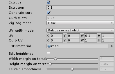
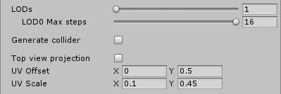
Collider LOD is the LOD from which mesh for the collider is taken.

Curve detail for individual LODs. Detail is defined by threshold for inserting vertices and beziér patch step. Vertices inserted when change of area by insertion between following steps exceeds the threshold.

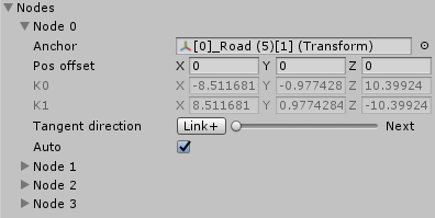
Anchor sets position of node relative to transform, If Anchor is set, Pos offset is in its coordinates, otherwise in global coordinates.
Tangent direction blends the direction between direction to previous and next nodes, or anchor Z axis and neigbouring node in case of last or first node. Link+ button switches between blending to anchor Z+ and Z-.
K0 and K1 are tangents, manual editing unlocked by disabling Auto.
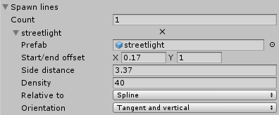
Spawn objects along spline. Lateral offset can be modulated by Relative to. Selection contains width profile curves of roads on same spline.
Rotation of spawned objects can be left same for all, or pointing in tangent direction, or pointing in tangent direction with y axis kept upwards.
Generates mesh by repeating and bending provided mesh along spline. Shape can be modulated by width profiles of roads on same spline.

Main mesh and start and end caps can be set for each LOD individually.

Crossroads
Scale on terrain sets width of heightmap edit.

Inner and outer radius of roundabout, UV offset on inner vertices number of vertices in connection parts of roundabout.

LODi Max steps sets the maximal number of connection and curve vertex steps for each LOD levels.
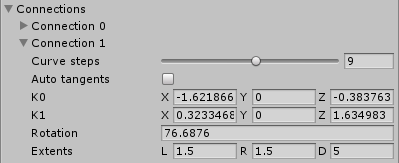
Curve steps sets number of vertices between connections.
With Auto tangent disabled, tangents K0 and K1 can be set manually.
Rotation sets direction of connection, Extents sets its length and left and right width.
Extents sets width and height of sidewalk. UVs can be configured for sidewalk top and curb separately.
